
(قسمت 4/6)++++

فرآیندهای حرارتی یا تبخیر ، تمام آب باقیمانده را تبخیر می کند ، آن را جمع آوری می کند و برای استفاده مجدد هدایت می کند. ضایعاتی که از آن باقی مانده است به سمت تبلور می رود که تمام آب را جوش می آورد تا اینکه همه ناخالصی ها متبلور شوند و به صورت جامد فیلتر شوند.
پس از مرحله پیش تغلیظ پساب، مرحله بعدی استفاده از فرآیندهای حرارتی یا تبخیر برای تولید جامد و استفاده مجدد از آب تبخیر شده است. تبخیر در اصل انتقال گرما به مایع در حال جوش با هدف تغلیظ یک ماده جامد غیر فرار از یک حلال که معمولا آب است، با جوشاندن حلال است. فرآیند تبخیر قبل از اینکه حلشونده شروع به رسوب نماید، متوقف میشود که به عنوان تبلور در نظر گرفته میشود.

پساب شور خروجی از تبخیرکننده به متبلورساز چرخشی میرود که در آن آب فراتر از حلالیت آلایندهها و کریستالهای تشکیل شده تغلیظ میشود. محصول حاصل از طریق فیلتر پرس یا سانتریفیوژ آبگیری میشود و به مرکز تبلور بازگردانده میشود.
تبخیر کننده ها دارای مبدل حرارتی هستند که وظیفه آن جوشاندن محلول است و آن ها همچنین دارای روشی هستند که بخار را از محلول جوش جدا می کند. انواع تبخیر کننده ها را می توان با توجه به طول آن ها و موقعیت (افقی یا عمودی) لوله های تبخیر طبقه بندی کرد.

انتخاب تبخیر کنندهی مناسب به موارد زیر بستگی دارد:
• خوراک ورودی
• ویسکوزیته محلول (و افزایش آن در طی تبخیر)
• حساسیت تبخیر کننده به گرما و خوردگی
• ویژگی های رسوب گذاری
• ویزگی های کف زایی

تبخیر فیلم در حال سقوط یک روش تبخیر کارآمد از نظر انرژی است که آب را تا نقطه تبلور اولیه (فوق اشباع) متمرکز میکند. افزودن اسید، محلول را خنثی میکند، بنابراین در هنگام گرم کردن آن، مانع از رسوب و آسیب به مبدلهای حرارتی میشود. از هوادهی غالبا برای آزادسازی اکسیژن محلول، دی اکسید کربن و سایر گازهای غیرقابل تراکم استفاده میشود
امروزه استفاده از تبخیر کننده ها موثرترین و در عین حال اقتصادی ترین روش در تصفیه ی پساب های صنعتی می باشد که عمده ترین ویژگی ها و اصول حاکم در این دستگاه به شرح زیر می باشد:
– تبخیر نمودن در محفظه های خلاء در دماهای پایین با استفاده از پمپ های حرارتی (دارای قابلیت های فراوان و سادگی در نصب)
– تبخیر کننده های خلاء چند مرحله ای با هزینه ی مصرف انرژی پایین برای پساب هایی با حجم بالا
– متراکم نمودن بخار با دمای بالا، ابعاد کوچک و کم جا بودن ، مصرف انرژی مناسب
– کریستاله نمودن عناصر ارزشمند (منجمد کننده های مخصوص جهت بارزیابی نمک های فلزی)
انواع روشهای Evapration
پوند تبخیر – Evaporation pond
پوند (حوضچه) تبخیر، یک سطح مصنوعی بزرگ است که به منظور تبخیر مایع و محلول های صنعتی به وسیله قرار گرفتن در معرض نور خورشید در دمای محیط است. حوضچه تبخیر به منظور حذف بخش مایع پسماندها استفاده می شود که بطور گسترده وزن و حجم آن را کاهش خواهد داد و به پسماند اجازه خواهد داد تا به راحتی انتقال، تصفیه یا نگهداری شود.برکههای تبخیر کاربردهای گوناگون دارند. برکههای تبخیر نمک، از آب دریا نمک تولید میکنند. از آنها همچنین برای دور ریز آب نمک از واحد نمک زدایی استفاده میشود. در معدنها از برکههای برای جدا کردن سنگ معدن از آب استفاده میشود. برکهٔ تبخیر در سایتهای آلوده برای جدا کردن آب از پسماندهای خطرناک (که تا حد زیادی وزن و حجم آن را کاهش میدهد و اجازه میدهد تا زباله به راحتی جابجا، تصفیه و ذخیره شود)، بکار میرود. یک نکتهٔ مهم این است که تبخیر همان چگالش نیست هر چند تبخیر در یک محیط سربسته میتواند منجر به وضعیت چگالش شود همانگونه که رطوبت تبخیرشده در هوا «چگالیده» میشود و به فاز مایع بازمیگردد.

Single-Effect vs. Multiple-Effect

Fig.2, Single, and Multiple Effect Evaporators configurations.
There are three criteria that affect the performance of an evaporator,
- Capacity (kg vaporized / time)
- Economy (kg vaporized / kg steam input)
- Steam Consumption (kg / hr)
Where Consumption = Capacity / Economy.
Economy (or steam economy) is the kilograms of water vaporized from all the effects (per kilogram of steam used). For single effect evaporator, the steam economy is ca. 0.8 (<1), which translates to 0.8 tons of steam needed to evaporate 1 ton of water.
So as to decrease the evaporator steam economy, the multiple-effect design uses the exhaust vapors from the product to heat the downstream evaporation effect and reduce the steam consumption.
The capacity of a multiple-effect evaporator (n effects) is ca. n*single effect evaporator capacity and the economy is about 0.8*n.
Evaporators need also pumps, interconnecting pipes, and valves that are required for transfer of liquid from one effect to another effect and they increase both the CAPEX and OPEX of the process.
| Live Steam | Vapor | Steam Economy | |
| 1-effect plant | 1 kg/h | 1 kg/h | 100% |
| 3-effect plant | 1 kg/h | 3 kg/h | 33% |
Table 1, Decrease of the evaporator steam economy by using a three effect evaporator
Single Effect (SE)
- Small capacity but wasteful energy (1 kg steam vaporize 1 kg water)
- Overall temperature drop for a single effect is somewhat equal to multiple effects
Multiple Effect (ME)
- Each individual effect will have a smaller temperature difference, thus high area of heating surfaces
- Capital cost more costly
- Operating cost- steam economy, only required for the first effect (1 kg steam vaporizes 3 kg water)
-
Evaporator Types
The temperature of the feed has an important effect on the evaporator’s economy and performance. If it is not already at its boiling point, then heat effects must take place. If the feed is above the boiling point, flash evaporation is used at the entry.

Normally, the feed solution is heated with a pre-heat exchanger to reduce the evaporation heat demand by transferring heat from the hot condensate to the feed stream.
The heated feed is then mixed with the evaporator liquid and the mixture is heated by the main heat exchanger which can use steam, electricity, hot oil or other forms of available energy. The mixture boils, producing a concentrated liquid stream and a water vapor stream which can be discharged or condensed.
Vapor compression (VC) evaporation has been the norm ZLD technology for the last decades, recovering ca. 95 % water from the feed. The concentrated liquid stream (brine) can then be driven to a crystallizer in order to be solidified.
Evaporation is rather expensive and not economically feasible with large feed flow rates, which is why a pre-concentration step is applied to the ZLD process.
There are different kinds of evaporators,
-
falling film
-
rising film
-
forced circulation
-
scraped surface/thin film
-
combination evaporator
The main ones are,
- Falling Film Evaporators (FFEs)
FFEs have many energy-saving, multiple-effect evaporation, and mechanical vapor re-compression features. A FFE operates with a very small operating temperature and allows,
- easy controls
- fast start-up and shut down due to a minimal liquid hold-up
FFEs are chosen for viscous streams with small concentrations of suspended solids. An FFE has small to large flow rates capacity.
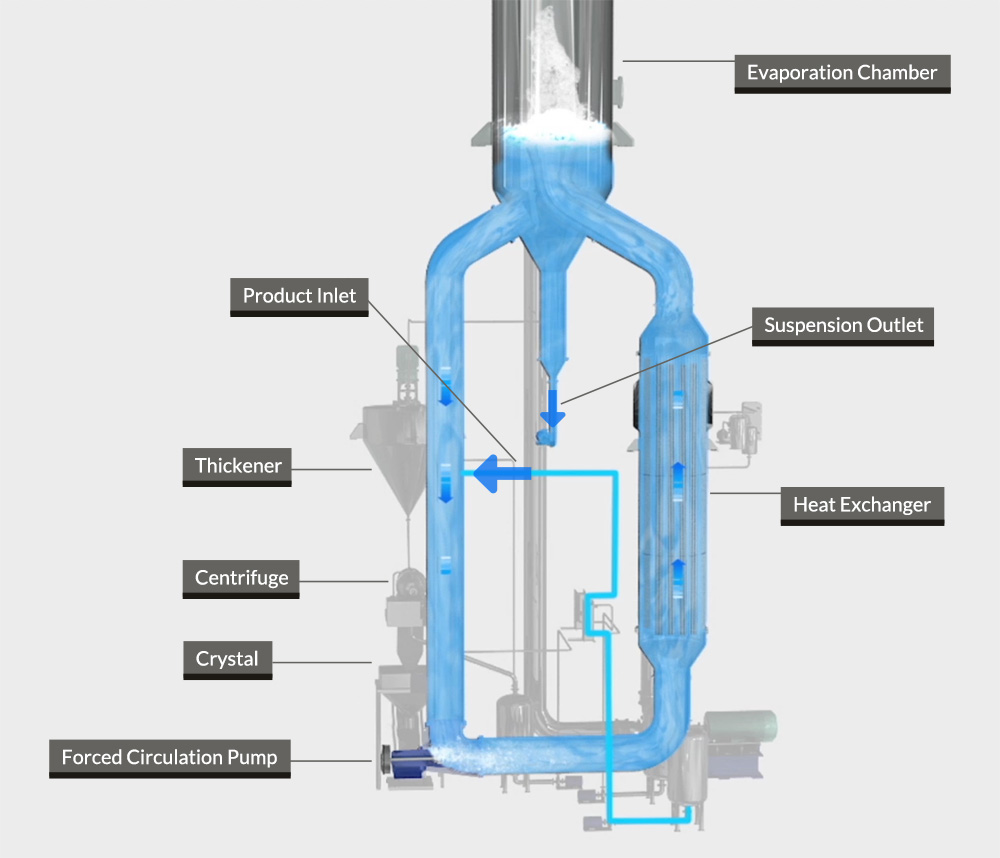
- Forced Circulation Evaporators (FCEs)
Because of the high circulation flow-rate and the evaporation taking place externally to the heat exchanger, FCEs are chosen for highly viscous streams containing a large concentration of suspended solids and fouling contaminants. It has medium to large flow rates capacity.
- Thin Film Evaporators (TFEs)/ Dryers
TFEs are mostly chosen in order to decrease the water content down to < 5% (crystallization). Like the FFEs, this technology is easy to control and fast to start up and shut down due to a very low liquid hold-up. TFEs are chosen for highly scaling products and highly viscous fluids. It has small to medium flow rates capacity.
Evaporators distillate stream is usually < 10 ppm TDS (Total Dissolved Solids). The most used is the FFE (also called brine concentrator) that can lead the feed concentration up to 300,000 ppm which leads to a boiling point rise (BPR) of the brine and requires either a large heat-transfer area (large CAPEX) or a large heat temperature (large OPEX).
- Process explanation
Evaporators can treat streams high chlorides concentration and theoretically separate the water from all of the dissolved species producing a stable solid product that can be landfilled and a high-quality distilled water product.
The steps in the evaporation process are (Fig.3),
- chemical addition (feed tank)
- preheating (feed preheater)
- deaeration
- primary evaporation (brine concentrator)

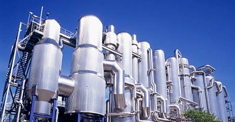
Fig.3, Evaporation process flow diagram and a photo of a real life module.

Steps 1&2; Acid is added to the feed tank to neutralize bicarbonate alkalinity in order for the solution to be preheated in the plate heat exchangers. Antiscalants are also added for preventing scaling in the preheaters with calcium carbonate.
Step 3; The pre-heated stream is degassed using steam from the evaporator (red line in Figure 3) to remove the dissolved carbon dioxide (alkalinity reduction), dissolved oxygen, and any other non-condensable gases in order to reduce the potential for corrosion of the evaporator.
Step 4; Most of the water evaporation takes place inside the brine concentrator vessel which is seeded with calcium sulfate to minimize scaling. The wastewater is typically saturated with calcium sulfate, which will precipitate and form scaling on the evaporator tubes. By using calcium sulfate seed crystals the dissolved calcium sulfate precipitates preferentially on the seed crystals rather than the evaporator tubes.
The process also requires electricity for the mechanical vapor compression (MVC) cycle. As MVC recycles the latent heat of vaporization, the energy input is quite low, in the range of 15 kWh/m3 of feed to minimize the size and cost of the vapor separator and compressor, evaporation occurs at atmospheric pressure.
- Energy saving
Some of the methods applied for minimizing the energy consumption of the evaporation plants include,
- Multiple effect arrangement (ME)
- Thermal vapor recompression (TVR)
- Mechanical vapor recompression (MVR)
- Mechanical vapor compression (MVC)
- Usage of waste energy
For evaporators, the MVC approach is the most widely used.
5.1 Mechanical Vapor Compression
In the MVC evaporator, heat is transferred to the circulating stream by condensing vapor from the compressor(s) (increasing the vapor’s temperature and pressure). In doing so it requires much less energy than a default evaporator.
During process (Fig.4), the vapor generated from the circulating stream has a large amount of energy in the form of latent heat at a temperature of the boiling wastewater. In order for the main heat exchanger to work, a higher temperature will be required. In order to get to the needed higher temperature, the vapor is compressed by the vapor compressor. Compressing the vapor raises its pressure (thus its saturation temperature as well) and produces the needed heat transfer in the main heat exchanger allowing for recycling the energy contained by the vapor, greatly improving the total energy efficiency.
- Feed wastewater goes from the feed pump to the feedstock heat exchanger and in the circulating stream. The feedstock heat exchanger heats transfers sensible heat from the hot condensate to the cooler feed.

Fig.4, Mechanical Vapor Compression process

- The recirculation pump circulates wastewater from the separation tank through the main heat exchanger, to the orifice plate, and back into the separation tank. The latent heat from the compressed vapor is transferred to the wastewater via the main heat exchanger.
- An orifice plate is used to reduce the pressure of the circulating stream. The downstream pressure is low enough to allow the flashing of the circulating stream into liquid and vapor components.
- The liquid and vapor then flow to the separation tank where they are separated. The liquid steam exits the tank at the bottom and flows back to the recirculation pump. The vapor stream exits the tank at the top and flows to the vapor compressor(s).
- A mist pad is provided at the top of the separation tank to remove small droplets of liquid from the vapor.
- The vapor compressor compresses the vapor (raising the temperature and pressure), and sends the vapor to the main heat exchanger, where it transfers its latent heat to the wastewater in the recirculation loop.
- High-temperature condensate exits the main heat exchanger and flows to the condensate tank, where any remaining vapor is separated. The hot condensate is then pumped to the feedstock heat exchanger, where it transfers sensible heat to the incoming feed wastewater.
- Upon reaching a steady-state at the target concentration, the concentrated wastewater is purged from the recirculation loop, using the residue valve. Depending on the energy balance, energy can be added to the system by electric heaters/process steam or excess energy can be removed from the system by the steam relief valve.

Advance Mist Cooling System

